
No products in the cart.


Note: ECG 3 is a development and prototyping tool. It is not intended to be used for a medical treatment of patients and other life-critical applications!
A high DC offset range allows it to be used with various electrodes, while the interrupt-based heart rate detection eliminates the need for the detection algorithm on the host MCU. A very high input impedance, coupled with the low-pass and high-pass filter options, allows user-adjustable tolerance vs accuracy factor. Embedded R-to-R detection and ECG functionalities simplify the firmware development. The inputs of the biopotential channel of the MAX30003 AFE IC are protected against the electrostatic discharge (ESD) and filtered against electromagnetic interferences (EMI), primarily generated by AC mains. Sequential power-up procedure reduces the inrush current through the electrodes, while fast recovery combined with the DC coupling helps to handle large voltage offsets between electrodes after the electrosurgery or defibrillation conditions occur.
ECG 3 click is equipped with the MAX30003 IC, an ultra-low power, single channel, integrated biopotential AFE, with the ECG and R-to-R detection functionality, from Maxim Integrated. To better understand the working principles of the ECG 3 click, some knowledge about how the heart works is required. There is a useful learning article about ECG monitoring, which can be a good starting point.

Electrocardiography is a process of recording electrical activity of the heart over a period of time, using electrodes placed on the body. These electrodes detect small electrical changes that arise from the electrophysiological pattern of the heart muscle. ECG 3 click is used to record a single-channel electrocardiogram. Electrodes can be attached to ECG 3 click via the onboard 3.5mm jack. ECG 3 click uses a three-electrode system, where two electrodes are connected to the positive and negative differential input of the MAX30003 (ECGP and ECGN pins), while the third electrode is connected to the GND. The Click board™ can be used with the cable and electrodes such as these: ECG/EMG cable, and ECG/EMG electrodes. In this case, the white electrode is the GND electrode.
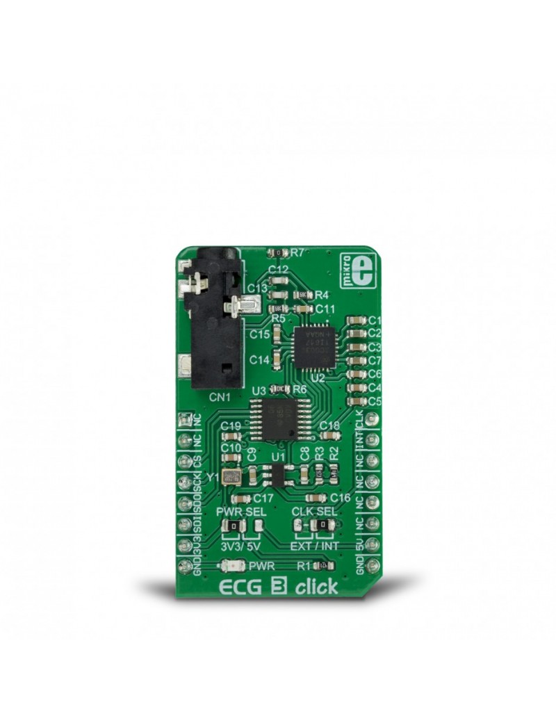
ECG 3 click is a complete solution for ECG and HR application development, utilizing a specialized IC with a clinical-grade analog front-end (AFE). ECG 3 click uses the MAX30003 IC, an ultra-low power, single-channel bio-sensor, which features a wide range of different options, making it an ideal solution for development of heart rate and ECG monitoring applications, fitness applications, for the ECG bio-authentication, and similar applications related to heart monitoring. ECG 3 click is also equipped with the 3.5mm electrodes connector, making it ready to be used out of the box.
ECG 3 click is supported by a mikroSDK compliant library, which includes functions that simplify software development. This Click board™ comes as a fully tested product, ready to be used on a system equipped with the mikroBUS™ socket.
| Type | Biometrics,ECG |
| Applications | ECG 3 click is an ideal solution for development of heart rate monitoring applications, fitness applications, for the ECG bio-authentication, and similar applications |
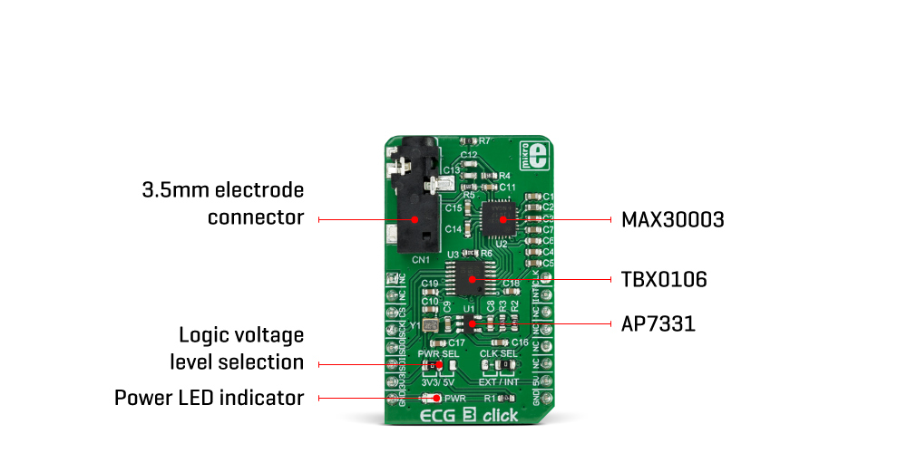
| On-board modules | MAX30003, an ultra-low power, single channel, integrated biopotential AFE, with the ECG and R - R detection, from Maxim Integrated; TBX0106, a bidirectional level translator from Texas Instruments, AP7331, a low dropout linear regulator from Diodes Incorporated |
| Key Features | Input ESD and EMI protection, high input impedance allows various electrodes to be used, a very large common mode rejection rate of over 100 dB (CMRR), signal conditioning reduces influence of movement artifacts, can be interfaced with both 3.3V and 5V MCUs |
| Interface | SPI |
| Feature | No ClickID |
| Compatibility | mikroBUS™ |
| Click board size | M (42.9 x 25.4 mm) |
| Input Voltage | 3.3V or 5V |
This table shows how the pinout on ECG 3 Click corresponds to the pinout on the mikroBUS™ socket (the latter shown in the two middle columns).
| Label | Name | Default | Description |
|---|---|---|---|
| PWR | PWR | - | Power LED indicator |
| JP1 | PWR SEL | Left | SDO/INTB pin mode selection: left position (SDO) - SPI Serial Data OUT on SDO pin, right position (INTB) - interrupt reporting on the INT pin |
| JP2 | CLK SEL | - | Clock source selection: left position - external (EXT), left position - onboard (INT) |
| CN1 | 3.5mm JACK | - | 3.5mm electrodes connector |
We provide a library for the ECG 3 click on our LibStock page, as well as a demo application (example), developed using MikroElektronika compilers. The demo can run on all the main MikroElektronika development boards.