


No products in the cart.
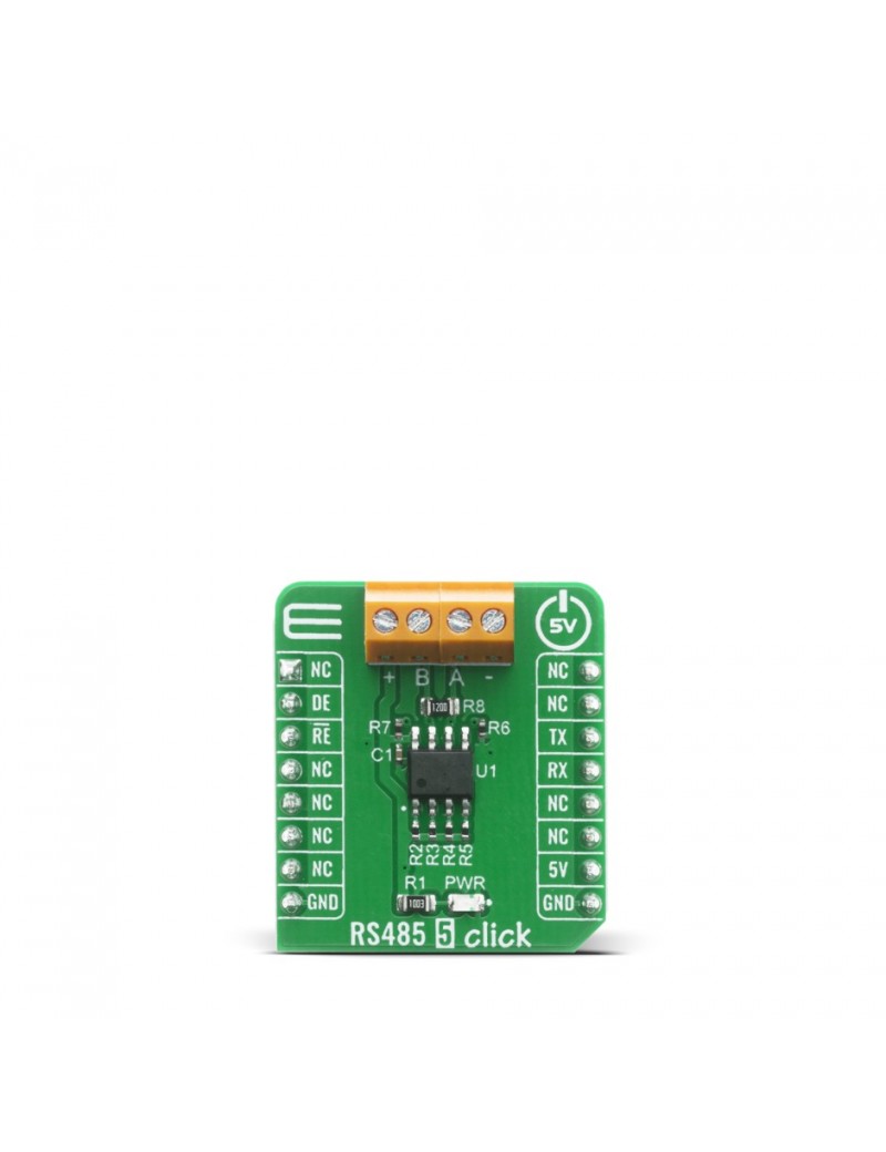
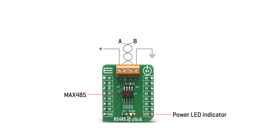
The RS485 5 Click is a Click board™ equipped with the MAX485, low-power, slew-rate-limited transceiver for RS-485 and RS-422 communication, from Analog Devices. This device supports half-duplex RS-485 communication and can be used as an interface between the TTL level UART and the RS485 communication bus. Thanks to the low power consumption and reduced slew-rate drivers that minimize EMI and reduce reflections caused by improperly terminated cables, error-free data transmission up to 250kbps is suported. RS485 5 Click is perfectly suitable for EMI-Sensitive Applications, such as industrial-control local area networks, building automation, HVAC systems, and many more.
RS485 5 Click is supported by a mikroSDK compliant library, which includes functions that simplify software development. This Click board™ comes as a fully tested product, ready to be used on a system equipped with the mikroBUS™ socket.
The RS485 5 Click is based around the MAX485 transceiver which draw between 120µA and 500µA of supply current when unloaded or fully loaded with disabled drivers. All parts operate from a single 5V supply. Driver is short-circuit current limited and is protected against excessive power dissipation by thermal shutdown circuitry that places the driver outputs into a high-impedance state. The receiver input has a fail-safe feature that guarantees a logic-high output if the input is open circuit.
The MAX485 slew rates are not limited, allowing it to transmit up to 2.5Mbps and half-duplex communication. In general, the maximal transfer speed is determined by the bus length, longer bus lines will result in less transfer speed. The RS485/422 line should be terminated at both ends in its characteristic impedance and stub lengths off the main line should be kept as short as possible to minimize the reflections. The RS-485/RS-422 standard covers line lengths up to 1220 meters (4000 feet).
Excessive output current and power dissipation caused by faults or by bus contention are prevented by two mechanisms. A foldback current limit on the output stage provides immediate protection against short circuits over the whole common-mode voltage range. In addition, a thermal shutdown circuit forces the driver outputs into a high-impedance state if the temperature rises excessively.
There are two 2-pole screw terminals on board (+, B, A, -) for connecting RS422/485 bus twisted pair cable, along with the GND and VCC. The terminal inputs labeled as “A” and “B” are used to connect the bus wires. GND and VCC rails can be used to provide the power supply for another node. Note that the VCC terminal is directly routed to the 5V rail of the mikroBUS™.
Pins used for communication are next:
This Click Board™ is designed to be operated only with 5V logic level. A proper logic voltage level conversion should be performed before the Click board™ is used with MCUs with logic levels of 3V3.
| Type | RS485 |
| Applications | Transceiver RS422/RS485 communication bus over UART interface for various automation systems, controllers, sensors and small embedded devices that can all share the same bus. |
| On-board modules | MAX485, low-power transceiver for RS-485 and RS-422 communication |
| Key Features | Transceiver draw between 120µA and 500µA of supply current when unloaded or fully loaded with disabled drivers. Driver is short-circuit current limited and is protected against excessive power dissipation by thermal shutdown circuitry. The receiver input has a fail-safe feature that guarantees a logic-high output if the input is open circuit. |
| Interface | GPIO,UART |
| Feature | No ClickID |
| Compatibility | mikroBUS™ |
| Click board size | S (28.6 x 25.4 mm) |
| Input Voltage | 5V |
This table shows how the pinout on RS485 5 Click corresponds to the pinout on the mikroBUS™ socket (the latter shown in the two middle columns).
| Notes | Pin | Pin | Notes | ||||
|---|---|---|---|---|---|---|---|
| NC | 1 | AN | PWM | 16 | NC | ||
| Receiver Output | DE | 2 | RST | INT | 15 | NC | |
| Drive Output | RE | 3 | CS | RX | 14 | TX | UART data transmit |
| NC | 4 | SCK | TX | 13 | RX | UART data receive | |
| NC | 5 | MISO | SCL | 12 | NC | ||
| NC | 6 | MOSI | SDA | 11 | NC | ||
| NC | 7 | 3.3V | 5V | 10 | 5V | Power Supply | |
| Ground | GND | 8 | GND | GND | 9 | GND | Ground |
| Label | Name | Default | Description |
|---|---|---|---|
| LD1 | PWR | - | Power LED Indicator |